Tuesday 18 July 2017

Permanent Magnet Moving Coil

Permanent Magnet Moving Coil

    Principle:
These instruments are used either as ammeters or voltmeters and are suitable for d.c work only. PMMCinstruments work on the principle that, when a current carrying conductor is placed in a magnetic field, a mechanical force acts on the conductor.
                    
v    Diagram:

PMMC


v    Construction:
A coil of thin wire is mounted on an aluminum frame (spindle) positioned between the poles of a U shaped permanent magnet which is made up of magnetic alloys like alnico.The coil is pivoted on the jeweled bearing and thus the coil is free to rotate. The current is fed to the coil through spiral springs which are two in numbers. The coil which carries a current, which is to be measured, moves in a strong magnetic field produced by a permanent magnet and a pointer is attached to the spindle which shows the measured value.
  Working:
When a current flow through the coil, it generates a magnetic field which is proportional to the current in case of an ammeter. The deflecting torque is produced by the electromagnetic action of the current in the coil and the magnetic field. When the torques are balanced the moving coil will stopped and its angular deflection represent the amount of electrical current to be measured against a fixed reference, called a scale. If the permanent magnet field is uniform and the spring linear, then the pointer deflection is also linear. The controlling torque is provided by two phosphorous bronze flat coiled helical springs. These springs serve as a flexible connection to the coil conductors. Damping is caused by the eddy current set up in the aluminum coil which prevents the oscillation of the coil.
v    Controlling Torque:
This torque is produced by the spring action and opposes the deflection torque so as the pointer can come to rest at the point where these two torques are equal (Electromagnetic torque = control spring torque). The value of control torque depends on the mechanical design of spiral springs and strip suspensions.
v    Damping Torque:
This torque ensures the pointer comes to an equilibrium position i.e. at rest in the scale without oscillating to give accurate reading. In PMMC as the coil moves in the magnetic filed, eddy current sets up in a metal former or core on which the coil is wound or in the circuit of the coil itself which opposes the motion of the coil resulting in slow swing of pointer and than come to rest quickly with very little oscillation.



Friday 28 April 2017

Errors in Measurement and Classification of Errors

True Value:

It is not possible to determine the true of quantity by experiment means. True value may be defined as the average value of an infinite number of measured values when average deviation due to various contributing factor will approach to zero.

Measured Value:

It may be defined as the approximated value of true value. It can be found out by taking means of several measured readings during an experiment, by applying suitable approximations on physical conditions. Now we are in a position to define static error. Static error is defined as the difference of the measured value and the true value of the quantity. Mathematically we can write an expression of error as, dA = Am - At where, dA is the static error Am is measured value and At is true value. It may be noted that the absolute value of error cannot be determined as due to the fact that the true value of quantity cannot be determined accurately. Let us consider few terms related to errors.

Types of Errors:
electrical information

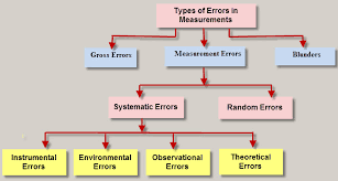
Basically there are three types of errors on the basis; they may arise from the source.

Gross Errors:

This category of errors includes all the human mistakes while reading, recording and the readings. Mistakes in calculating the errors also come under this category. For example while taking the reading from the meter of the instrument he may read 21 as 31. All these types of error are come under this category. Gross errors can be avoided by using two suitable measures and they are written below:
1.      A proper care should be taken in reading, recording the data. Also calculation of error should be done accurately.
2.      By increasing the number of experimenters we can reduce the gross errors. If each experimenter takes different reading at different points, then by taking average of more readings we can reduce the gross errors.

Systematic Errors:

In order to understand these kinds of errors, let us categorize the systematic errors as

Instrumental Errors:

These errors may be due to wrong construction, calibration of the measuring instruments. These types of error may be arises due to friction or may be due to hysteresis. These types of errors also include the loading effect and misuse of the instruments. Misuse of the instruments results in the failure to the adjust the zero of instruments. In order to minimize the gross errors in measurement various correction factors must be applied and in extreme condition instrument must be re-calibrated carefully.

Environmental Errors:

This type of error arises due to conditions external to instrument. External condition includes temperature, pressure, humidity or it may include external magnetic field. Following are the steps that one must follow in order to minimize the environmental errors:
·         Try to maintain the temperature and humidity of the laboratory constant by making some arrangements.
·         Ensure that there should not be any external magnetic or electrostatic field around the instrument.

Observational Errors:

As the name suggests these types of errors are due wrong observations. The wrong observations may be due to PARALLAX. In order to minimize the PARALLAX error highly accurate meters are required, provided with mirrored scales.

Random Errors:


After calculating all systematic errors, it is found that there are still some errors in measurement are left. These errors are known as random errors. Some of the reasons of the appearance of these errors are known but still some reasons are unknown. Hence we cannot fully eliminate these kinds of error.

Tuesday 11 April 2017

Electrical Switchgear Protection

Definition of Switchgear

A switchgear or electrical switchgear is a generic term which includes all the switching devices associated with mainly power system protection. It also includes all devices associated with control, metering and regulating of electrical power system. Assembly of such devices in a logical manner forms switchgear. In other words apparatus used for switching, controlling and protecting the electrical circuits and equipment is known as switchgear. This is very basic definition of switchgear.


Switchgear and Protection

We are all familiar with low voltage switches and re-warble fuses in our home. The switch is used to manually open and close the electrical circuit in our home and electrical fuse is used to protect our household electrical circuit from over current and short circuit faults. In same way every electrical circuit including high voltage electrical power system needs switching and protective devices. But in high voltage and extra high voltage system, this switching and protective scheme becomes complicated one for high fault current interruption in safe and secure way. In addition to that from commercial point of view every electrical power system needs measuring, control and regulating arrangement. Collectively the whole system is called switchgear and protection of power system. The electrical switchgear has been developing in various forms.
Switchgear protection plays a vital role in modern power system network, right from generation through transmission to distribution end. The current interruption device or switching device is called circuit breaker in switchgear protection system. The circuit breaker can be operated manually as when required and it is also operated during over current and short circuit or any other faults in the system by sensing the abnormality of system. The circuit breaker senses the faulty condition of system through protection relay and this relay is again actuated by faulty signal normally comes from current transformer or voltage transformer. The switchgear has to perform the function of carrying, making and breaking the normal load current like a switch and it has to perform the function of clearing the fault in addition to that it also has provision of metering and regulating the various parameters of electrical power system. Thus the switchgear includes circuit breaker, current transformer, voltage transformer, protection relay, measuring instrument, electrical switch, electrical fuse, miniature circuit breaker, lightening arrestor or surge arrestor, electrical isolator and other associated equipment.
Electric switchgear is necessary at every switching point in the electrical power system. There are various voltage levels and hence various fault levels between the generating stations and load centers. Therefore various types of switchgear assembly are required depending upon different voltage levels of the system. Besides the power system network, electrical switchgear is also required in industrial works, industrial projects, domestic and commercial buildings.
                                      

Friday 31 March 2017

Power Plants and Types of Power Plant

What is Power Plant?

A power plant or a power generating station, is basically an industrial location that is utilized for the generation and distribution of electric power in mass scale, usually in the order of several 1000 Watts. These are generally located at the sub-urban regions or several kilometers away from the cities or the load centers, because of its requisites like huge land and water demand, along with several operating constraints like the waste disposal etc. For this reason, a power generating station has to not only take care of efficient generation but also the fact that the power is transmitted efficiently over the entire distance. And that’s why, the transformer switch yard to regulate transmission voltage also becomes an integral part of the power plant.


Types of Power Station

A power plant can be of several types depending mainly on the type of fuel used. Since for the purpose of bulk power generation, only thermal, nuclear and hydro power comes handy, therefore a power generating station can be broadly classified in the 3 above mentioned types. Let us have a look in these types of power stations in details.

Thermal Power Station
A thermal power station or a coal fired thermal power plant is by far, the most conventional method of generating electric power with reasonably high efficiency. It uses coal as the primary fuel to boil the water available to superheated steam for driving the steam turbine. The steam turbine is then mechanically coupled to an alternator rotor, the rotation of which results in the generation of electric power. Generally in India, bituminous coal or brown coal are used as fuel of boiler which has volatile content ranging from 8 to 33 % and ash content 5 to 16 %. To enhance the thermal efficiency of the plant, the coal is used in the boiler in its pulverized form. In coal fired thermal power plant, steam is obtained in very high pressure inside the steam boiler by burning the pulverized coal. This steam is then super heated in the super heater to extreme high temperature. This super heated steam is then allowed to enter into the turbine, as the turbine blades are rotated by the pressure of the steam. The turbine is mechanically coupled with alternator in a way that its rotor will rotate with the rotation of turbine blades. After entering into the turbine, the steam pressure suddenly falls leading to corresponding increase in the steam volume. After having imparted energy into the turbine rotors, the steam is made to pass out of the turbine blades into the steam condenser of turbine. In the condenser, cold water at ambient temperature is circulated with the help of pump which leads to the condensation of the low pressure wet steam. Then this condensed water is further supplied to low pressure water heater where the low pressure steam increases the temperature of this feed water, it is again heated in high pressure. This outlines the basic working methodology of a thermal power plant.

Nuclear Power Station


The nuclear power generating stations are similar to the thermal stations in more ways than one. However, the exception here is that, radioactive elements like uranium and thorium are used as the primary fuel in place of coal. Also in a nuclear station the furnace and the boiler are replaced by the nuclear reactor and the heat exchanger tubes. For the process of nuclear power generation, the radioactive fuels are made to undergo fission reaction within the nuclear reactors. The fission reaction, propagates like a controlled chain reaction and is accompanied by unprecedented amount of energy produced, which is manifested in the form of heat. This heat is then transferred to the water present in the heat exchanger tubes. As a result, super-heated steam at very high temperature is produced. Once the process of steam formation is accomplished, the remaining process is exactly similar to a thermal power plant, as this steam will further drive the turbine blades to generate electricity.

Hydro-Electric Power Station
In Hydro-electric plants the energy of the falling water is utilized to drive the turbine which in turn runs the generator to produce electricity. Rain falling upon the earth’s surface has potential energy relative to the oceans towards which it flows. This energy is converted to shaft work where the water falls through an appreciable vertical distance. The hydraulic power is therefore a naturally available renewable energy given by the eqn: P = gρ QH Where, g = acceleration due to gravity = 9.81 m/sec 2 ρ = density of water = 1000 kg/m 3 H = height of fall of water. This power is utilized for rotating the alternator shaft, to convert it to equivalent electrical energy. An important point to be noted is that, the hydro-electric plants are of much lower capacity compared to their thermal or nuclear counterpart. For this reason hydro plants are generally used in scheduling with thermal stations, to serve the load during peak hours. They in a way assist the thermal or the nuclear plant to deliver power efficiently during periods of peak hours.

Diesel Power Station
For generating electrical power, it is essential to rotate the rotor of an alternator by means of a prime mover. The prime mover can be driven by different methods. Using diesel engine as prime mover is one of the popular methods of generating power. When prime mover of the alternators is diesel engine, the power station is called diesel power station. The mechanical power required for driving alternator comes from combustion of diesel. As the diesel costs high, this type of power station is not suitable for producing power in large scale in our country. But for small scale production of electric power, and where, there is no other easily available alternatives of producing electric power, diesel power station are used. Steam power stations and hydro power plants are mainly used to produce maximum portion of the electrical load demands. But for steam power station, sufficient supply of coal and water are required.


Wednesday 22 March 2017

INDUCTION MOTOR

INDUCTION MOTOR

One of the most common electrical motor used in most applications which is known as induction motor. This motor is also called as asynchronous motor because it runs at a speed less than its synchronous speed. Here we need to define what synchronous speed is. Synchronous speed is the speed of rotation of the magnetic field in a rotary machine and it depends upon the frequency and number poles of the machine. An induction motor always runs at a speed less than synchronous speed because the rotating magnetic field which is produced in the stator will generate flux in the rotor which will make the rotor to rotate, but due to the lagging of flux current in the rotor with flux current in the stator, the rotor will never reach to its rotating magnetic field speed i.e. the synchronous speed. There are basically two types of induction motor that depend upon the input supply - single phase induction motor and three phase induction motor. Single phase induction motor is not a self-starting motor which we will discuss later and three phase induction motorist a self-starting motor.

Working Principle of Induction Motor:

We need to give double excitation to make a machine to rotate. For example if we consider a DC motor, we will give one supply to the stator and another to the rotor through brush arrangement. But in induction motor we give only one supply, so it is really interesting to know that how it works. It is very simple, from the name itself we can understand that induction process is involved. Actually when we are giving the supply to the stator winding, flux will generate in the coil due to flow of current in the coil. Now the rotor winding is arranged in such a way that it becomes short circuited in the rotor itself. The flux from the stator will cut the coil in the rotor and since the rotor coils are short circuited, according to Faraday's law of electromagnetic induction, current will start flowing in the coil of the rotor. When the current will flow, another flux will get generated in the rotor. Now there will be two flux, one is stator flux and another is rotor flux and the rotor flux will be lagging w.r.t to the stator flux. Due to this, the rotor will feel a torque which will make the rotor to rotate in the direction of rotating magnetic flux. So the speed of the rotor will be depending upon the ac supply and the speed can be controlled by varying the input supply. This is the working principle of an induction motor of either type – single and three phase.
Types Induction Motor:

Single Phase Induction Motor:

Split phase induction motor
Capacitor start induction motor
Capacitor start capacitor run induction motor
Shaded pole induction motor
Three Phase Induction Motor

Squirrel cage induction motor
Slip ring induction motor

Why is Three Phase Induction Motor Self Starting?

In three phase system, there are three single phase line with 120° phase difference. So the rotating magnetic field is having the same phase difference which will make the rotor to move. If we consider three phases a, b and c, when phase a is magnetized, the rotor will move towards the phase a winding a, in the next moment phase b will get magnetized and it will attract the rotor and then phase c. So the rotor will continue to rotate.

Why Single Phase Induction Motor is not Self Starting?

It will be having only one phase still it makes the rotor to rotate, so it is quite interesting. Before that we need to know why single phase induction motor is not a self-starting motor and how the problem is overcome. We know that the ac supply is a sinusoidal wave and it produces pulsating magnetic field in uniformly distributed stator winding. Since pulsating magnetic field can be assumed as two oppositely rotating magnetic fields, there will be no resultant torque produced at the starting and due to this the motor does not run. After giving the supply, if the rotor is made to rotate in either direction by external force, then the motor will start to run. This problem has been solved by making the stator winding into two winding, one is main winding and another is auxiliary winding and a capacitor is fixed in series with the auxiliary winding. This will make a phase difference when current will flow through the both coils. When there will be phase difference, the rotor will generate a starting torque and it will start to rotate. Practically we can see that the fan does not rotate when the capacitor is disconnected from the motor but if we rotate with hand it will start to rotate. So this is the reason of using capacitor in the single phase induction motor. There are several advantages of induction motor which makes this motor to have wider application. It is having good efficiency up to 97%. But the speed of the motor varies with the load given to the motor which is an disadvantage of this motor. The direction of rotation of induction motor can easily be changed by changing the sequence of three phase supply, i.e. if RYB is in forward direction, the RBY will make the motor to rotate in reverse direction. This is in the case of three phase motor but in single phase motor, the direction can be reversed by reversing the capacitor terminals in the winding.

Tuesday 14 March 2017

Principle of DC Generator


Working Principle of DC Generator


There are two types of generators, one is ac generator and other is DC generator. Whatever may be the types of generators, it always converts mechanical power to electrical power. An AC  generator produces alternating power. A DC generator produces direct power. Both of these generators produce electrical power, based on same fundamental principle of Faraday's law of electromagnetic induction. According to this law, when a conductor moves in a magnetic field it cuts magnetic lines of force, due to which an emf is induced in the conductor. The magnitude of this induced emf depends upon the rate of change of flux (magnetic line force) linkage with the conductor. This emf will cause a current to flow if the conductor circuit is closed .Hence the most basic tow essential parts of a generator are
1) Magnetic Field
2) Conductor Which Moves Inside The Magnetic Field.


It is seen that in the first half of the revolution current flows always along ABLMCD i.e. brush no 1 in contact with segment a. In the next half revolution, in the figure the direction of the induced current in the coil is reversed. But at the same time the position of the segments a and b are also reversed which results that brush no 1 comes in touch with the segment b. Hence, the current in the load resistance again flows from L to M. The wave from of the current through the load circuit is as shown in the figure. This current is unidirectional.

 This is basic working principle of DC generator, explained by single loop generator model. The position of the brushes of DC generator is so arranged that the change over of the segments a and b from one brush to other takes place when the plane of rotating coil is at right angle to the plane of the lines of force. It is so become in that position, the induced emf in the coil is zero.


Working and Operating Principle of DC Motor

Working and Operating Principle of DC Motor

A DC motor in simple words is a device that converts electrical energy (direct current system) into mechanical energy. It is of vital importance for the industry today, and is equally important for engineers to look into the working principle of DC motor in details that has been discussed in this article. In order to understand the operating principle of DC motor we need to first look into its constructional feature.

The very basic construction of a DC motor contains a current carrying armature which is connected to the supply end through commutator segments and brushes. The armature is placed in between north south poles of a permanent or an electromagnet as shown in the diagram above.
As soon as we supply direct current in the armature, a mechanical force acts on it due to electromagnetic effect of the magnet. Now to go into the details of the operating principle of DC motor its important that we have a clear understanding of Fleming’s left hand rule to determine the direction of force acting on the armature conductors of DC motor.
If a current carrying conductor is placed in a magnetic field perpendicularly, then the conductor experiences a force in the direction mutually perpendicular to both the direction of field and the current carrying conductor. Fleming’s left hand rule says that if we extend the index finger, middle finger and thumb of our left hand perpendicular to each other, in such a way that the middle finger is along the direction of current in the conductor, and index finger is along the direction of magnetic field i.e. north to south pole, then thumb indicates the direction of created mechanical force.
For clear understanding the principle of DC motor we have to determine the magnitude of the force, by considering the diagram below.
We know that when an infinitely small charge dq is made to flow at a velocity ‘v’ under the influence of an electric field E, and a magnetic field B, then the Lorentz Force dF experienced by the charge is given by:-


For the operation of DC motor, considering E = 0
i.e. it’s the cross product of dq v and magnetic field B.
Where dL is the length of the conductor carrying charge q.
From the 1st diagram we can see that the construction of a DC motor is such that the direction of current through the armature conductor at all instance is perpendicular to the field. Hence the force acts on the armature conductor in the direction perpendicular to the both uniform field and current is constant.
So if we take the current in the left hand side of the armature conductor to be I, and current at right hand side of the armature conductor to be − I, because they are flowing in the opposite direction with respect to each other. Then the force on the left hand side armature conductor,
Similarly force on the right hand side conductor
Therefore, we can see that at that position the force on either side is equal in magnitude but opposite in direction. And since the two conductors are separated by some distance w = width of the armature turn, the two opposite forces produces a rotational force or a torque that results in the rotation of the armature conductor. Now let's examine the expression of torque when the armature turn crate an angle of α (alpha) with its initial position. The torque produced is given by,
Where, α (alpha) is the angle between the plane of the armature turn and the plane of reference or the initial position of the armature which is here along the direction of magnetic field. The presence of the term cosα in the torque equation very well signifies that unlike force the torque at all position is not the same. It in fact varies with the variation of the angle α (alpha). To explain the variation of torque and the principle behind rotation of the motor let us do a step wise analysis.

Thursday 2 March 2017

Transformer

Transformer
Definition of Transformer:

Electrical power transformer is a static device which transforms electrical energy from one circuit to another without any direct electrical connection and with the help of mutual induction between two windings. It transforms power from one circuit to another without changing its frequency but may be in different voltage level. This is a very short and simple definition of transformer, as we will go through this portion of tutorial related to electrical power transformer, we will understand more clearly and deeply "what is transformer ?" and basic theory of transformer.

Working Principle of Transformer:


The working principle of transformer is very simple. It depends upon Faraday's law of electromagnetic induction. Actually, mutual induction between two or more winding is responsible for transformation action in an electrical transformer.

Basic Theory of Transformer:


Say you have one winding which is supplied by an alternating electrical source. The alternating current through the winding produces a continually changing flux or alternating flux that surrounds the winding. If any other winding is brought nearer to the previous one, obviously some portion of this flux will link with the second. As this flux is continually changing in its amplitude and direction, there must be a change in flux linkage in the second winding or coil. According to Faraday's law of electromagnetic induction, there must be an EMF induced in the second. If the circuit of the later winding is closed, there must be an current flowing through it. This is the simplest form of electrical power transformer and this is the most basic of working principle of transformer. For better understanding, we are trying to repeat the above explanation in a more brief way here. Whenever we apply alternating current to an electric coil, there will be an alternating flux surrounding that coil. Now if we bring another coil near the first one, there will be an alternating flux linkage with that second coil. As the flux is alternating, there will be obviously a rate of change in flux linkage with respect to time in the second coil. Naturally emf will be induced in it as per Faraday's law of electromagnetic induction.
Theory of transformer:

The winding which takes electrical power from the source, is generally known as primary winding of transformer. Here in our above example it is first winding. The winding which gives the desired output voltage due to mutual induction in the transformer, is commonly known as secondary winding of transformer. Here in our example it is second winding. The above mentioned form of transformer is theoretically possible but not practically, because in open air very tiny portion of the flux of the first winding will link with second; so the current that flows through the closed circuit of later, will be so small in amount that it will be difficult to measure. The rate of change of flux linkage depends upon the amount of linked flux with the second winding. So, it is desired to be linked to almost all flux of primary winding to the secondary winding. This is
effectively and efficiently done by placing one low reluctance path common to both of the winding. This low reluctance path is
core of transformer, through which maximum number of flux produced by the primary is passed through and linked with the secondary

Wednesday 1 March 2017

Construction of Power Cable

Construction of Power Cable
There are various parts of a cable to be taken care of during construction. The power cable mainly consists of:
  1. Conductor
  2. Insulation
  3. LAY for Multicore cables only
  4. Bedding
  5. Bedding
  6. Outer Sheath


Conductor:

Conductors are the only power carrying path in a power cable. Conductors are of different materials. Mainly in cable industry we use copper (ATC, ABC) and aluminum conductors for power cables. There are different types of conductor as Class 1: solid, Class 2 stranded, Class 5 flexible, Class 6 Extra flexible (Mostly used for cords and welding) etc. Conductor sizes are identified with conductor resistance.

Insulation:

The insulation provided on each conductor of a cable by mainly PVC (Poly Vinyl Chloride), XLPE (Cross-linked Polyethylene), RUBBER (Various Types of Rubber). Insulating material is based on operating temperature. Cores are identified by color coding by using different coolers on insulation or by number printing on cores

Beading:

This portion of the cable is also known as inner sheath. Mostly it is used in Multi core cables. It works as binder for insulated conductors together in multi-core power cables and provides bedding to armor/braid. This portion of the cable is mainly made of PVC( PVC ST-1, PVC ST-2 ), RUBBER (CSP SE-3, CSP SE-4 and PCP SE-3, PCP SE-4, HOFR SE-3 HOFR SE-4, HD HOFR SE-3 ETC)

Armoring:

There are mainly G.I. WIRE ARMOURING, G.I. STEEL STRIP armoring. It is done by placing G.I. WIREs, GI or STEEL STRIPs one by one on inner sheath. Armoring is a process which is done mainly for providing earthling shield to the current carrying conductors as well as it is also used for earthling purpose of the cable for safety. When there is any insulation failure in the conductor, the fault current gets enough paths to flow through the amour if it is properly earthed. Providing extra mechanical protection and strength to cable is an important added advantage of armoring. In MINING CABLES it is done for conductance.

Outer Sheath:

This is outermost cover of the cable normally made of PVC (Poly Vinyl Chloride), RUBBER (Various Types of Rubber) and often the same material as the bedding. It is provided over the amour for overall mechanical, weather, chemical and electrical protection. Outer sheath is protection offered to cable not much electrically but more mechanically.

Friday 3 February 2017

DC Traction System

DC Traction System


  • The transformation and high voltage generation of dc is very inconvenient to the dc supply used is at normally 600 V and this voltage is almost universal for use in urban and suburban railways.
  • For direct current equipment, the series motor is universally employed as its speed-torque characteristics are best suited to traction requirements.
  • Generally two or more motors are used in single equipment and these are coupled in series or in parallel to give the different running speeds required.
  • The motors are initially connected in series with starting rheostats across the contact line and rails, the rheostats are then cut out in steps, keeping roughly constant current until the motors are running in full series.
  • After this the motors are rearranged in parallel, again with rheostats, the rheostats are cut out in steps, leaving the motors in full parallel. The power input remains approximately constant during the series notching, then jumps to twice this value during the parallel notching.
  • Thus a 4 motor unit will have three economical speeds when the motors are running in series, series - parallel connections. The rheostats are operated electro magnetically or electro-pneumatically.


Braking System:

  • When a locomotive is running at certain speed and if it is to be stopped within a short distance brakes are to be applied. For this purpose brake shoes are provided which are pressed against the wheels for retardation.
  • Steam and diesel locomotives have pneumatic braking system. Some electrical methods of braking have also been devised which are used mainly to step electric motors.
  • During electric braking the kinetic energy of the motor and the coupled mechanism is steadily dissipated in some form or other and the speed of the machine goes on reducing.

Thursday 2 February 2017

Electrical Drive

Electrical Drive

  • Whenever the term electric motor or electrical generator is used, we tend to think that the speed of rotation of these machines is totally controlled only by the applied voltage and frequency of the source current.
  • But the speed of rotation of an electrical machine can be controlled precisely also by implementing the concept of drive.
  • The main advantage of this concept is, the motion control is easily optimized with the help of drive. In very simple words, the systems which control the motion of the electrical machines, are known as electrical drives.
  • A typical drive system is assembled with a electric motor (may be several) and a sophisticated control system that controls the rotation of the motor shaft.
  • Now days, this control can be done easily with the help of software. So, the controlling becomes more and more accurate and this concept of drive also provides the ease of use.
  • This drive system is widely used in large number of industrial and domestic applications like factories, transportation systems, textile mills, fans, pumps, motors, robots etc.
  • Drives are employed as prime movers for diesel or petrol engines, gas or steam turbines, hydraulic motors and electric motors.
  • Now coming to the history of electrical drives, this was first designed in Russia in the year 1838 by B.S.Iakobi, when he tested a DC electric motor supplied from a storage battery and propelled a boat.
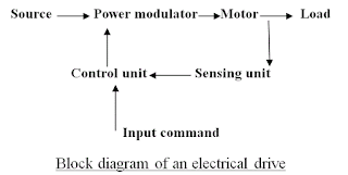
  • Even though the industrial adaptation occurred after many years as around 1870. Today almost everywhere the application of electric drives is seen. The very basic block diagram an electric drives is shown below.
  • The load in the figure represents various types of equipments which consists of electric motor, like fans, pumps, washing machines etc.


Copyright @ 2013 Electrical Information.

Designed by Templateiy & CollegeTalks